Inductor Current Phase Shift . understanding inductors in series and parallel configurations is essential as it affects the total inductance and impacts. the phasor diagram shows the applied voltage (e) vector leading (above) the current (i) vector by the amount of the phase angle differential due to the relationship between voltage and current in an inductive circuit. the two words help to remember that for a c component (capacitor) in the circuit i is before e (current leads) and for an l (inductor), e is before i (voltage leads). the opposition to current flow through an ac inductor is called inductive reactance and which depends lineally on the supply frequency. when capacitors or inductors are involved in an ac circuit, the current and voltage do not peak at the same time.
from www.numerade.com
the two words help to remember that for a c component (capacitor) in the circuit i is before e (current leads) and for an l (inductor), e is before i (voltage leads). when capacitors or inductors are involved in an ac circuit, the current and voltage do not peak at the same time. understanding inductors in series and parallel configurations is essential as it affects the total inductance and impacts. the phasor diagram shows the applied voltage (e) vector leading (above) the current (i) vector by the amount of the phase angle differential due to the relationship between voltage and current in an inductive circuit. the opposition to current flow through an ac inductor is called inductive reactance and which depends lineally on the supply frequency.
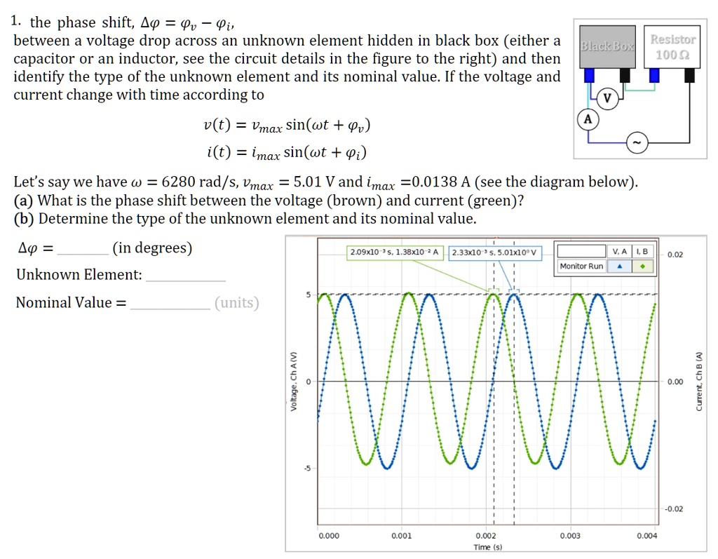
SOLVED The phase shift, θ, between a voltage drop across an unknown
Inductor Current Phase Shift understanding inductors in series and parallel configurations is essential as it affects the total inductance and impacts. the two words help to remember that for a c component (capacitor) in the circuit i is before e (current leads) and for an l (inductor), e is before i (voltage leads). when capacitors or inductors are involved in an ac circuit, the current and voltage do not peak at the same time. understanding inductors in series and parallel configurations is essential as it affects the total inductance and impacts. the opposition to current flow through an ac inductor is called inductive reactance and which depends lineally on the supply frequency. the phasor diagram shows the applied voltage (e) vector leading (above) the current (i) vector by the amount of the phase angle differential due to the relationship between voltage and current in an inductive circuit.
From www.researchgate.net
Current twophase common inductor LLC resonant converter with current Inductor Current Phase Shift the phasor diagram shows the applied voltage (e) vector leading (above) the current (i) vector by the amount of the phase angle differential due to the relationship between voltage and current in an inductive circuit. the opposition to current flow through an ac inductor is called inductive reactance and which depends lineally on the supply frequency. when. Inductor Current Phase Shift.
From eepower.com
Complex Numbers, Phasors And Phase Shift Chapter 2 Analysis of AC Inductor Current Phase Shift understanding inductors in series and parallel configurations is essential as it affects the total inductance and impacts. when capacitors or inductors are involved in an ac circuit, the current and voltage do not peak at the same time. the two words help to remember that for a c component (capacitor) in the circuit i is before e. Inductor Current Phase Shift.
From www.allaboutcircuits.com
Understanding Phase Shift in Analog Circuits Technical Articles Inductor Current Phase Shift when capacitors or inductors are involved in an ac circuit, the current and voltage do not peak at the same time. the phasor diagram shows the applied voltage (e) vector leading (above) the current (i) vector by the amount of the phase angle differential due to the relationship between voltage and current in an inductive circuit. the. Inductor Current Phase Shift.
From www.researchgate.net
Details of inductor current IL and output voltage VLX of the Inductor Current Phase Shift when capacitors or inductors are involved in an ac circuit, the current and voltage do not peak at the same time. the phasor diagram shows the applied voltage (e) vector leading (above) the current (i) vector by the amount of the phase angle differential due to the relationship between voltage and current in an inductive circuit. the. Inductor Current Phase Shift.
From www.researchgate.net
Normalized inductor RMS current vs. phaseshift α at different power Inductor Current Phase Shift the phasor diagram shows the applied voltage (e) vector leading (above) the current (i) vector by the amount of the phase angle differential due to the relationship between voltage and current in an inductive circuit. understanding inductors in series and parallel configurations is essential as it affects the total inductance and impacts. the two words help to. Inductor Current Phase Shift.
From learnchannel-tv.com
AC Inductive Circuits Inductor Current Phase Shift the phasor diagram shows the applied voltage (e) vector leading (above) the current (i) vector by the amount of the phase angle differential due to the relationship between voltage and current in an inductive circuit. the two words help to remember that for a c component (capacitor) in the circuit i is before e (current leads) and for. Inductor Current Phase Shift.
From circuitdatamoeller.z19.web.core.windows.net
Ac Rlc Circuits Phasor Diagrams Inductor Current Phase Shift the opposition to current flow through an ac inductor is called inductive reactance and which depends lineally on the supply frequency. understanding inductors in series and parallel configurations is essential as it affects the total inductance and impacts. the phasor diagram shows the applied voltage (e) vector leading (above) the current (i) vector by the amount of. Inductor Current Phase Shift.
From www.webassign.net
Lab 9 AC Circuits Inductor Current Phase Shift when capacitors or inductors are involved in an ac circuit, the current and voltage do not peak at the same time. understanding inductors in series and parallel configurations is essential as it affects the total inductance and impacts. the opposition to current flow through an ac inductor is called inductive reactance and which depends lineally on the. Inductor Current Phase Shift.
From studylib.net
Voltage/Current Phase Angle Inductor Current Phase Shift the phasor diagram shows the applied voltage (e) vector leading (above) the current (i) vector by the amount of the phase angle differential due to the relationship between voltage and current in an inductive circuit. understanding inductors in series and parallel configurations is essential as it affects the total inductance and impacts. the two words help to. Inductor Current Phase Shift.
From schematickalksburgzi.z13.web.core.windows.net
Phase Shift Voltage Circuit Inductor Current Phase Shift when capacitors or inductors are involved in an ac circuit, the current and voltage do not peak at the same time. the opposition to current flow through an ac inductor is called inductive reactance and which depends lineally on the supply frequency. the phasor diagram shows the applied voltage (e) vector leading (above) the current (i) vector. Inductor Current Phase Shift.
From arbiter-mnrbj.blogspot.com
☑ Inductor Voltage And Current Graph Inductor Current Phase Shift the opposition to current flow through an ac inductor is called inductive reactance and which depends lineally on the supply frequency. the phasor diagram shows the applied voltage (e) vector leading (above) the current (i) vector by the amount of the phase angle differential due to the relationship between voltage and current in an inductive circuit. understanding. Inductor Current Phase Shift.
From in.pinterest.com
RC PHASE SHIFT OSCILLATOR 🔽 . . A phaseshift oscillator is a linear Inductor Current Phase Shift understanding inductors in series and parallel configurations is essential as it affects the total inductance and impacts. the two words help to remember that for a c component (capacitor) in the circuit i is before e (current leads) and for an l (inductor), e is before i (voltage leads). the phasor diagram shows the applied voltage (e). Inductor Current Phase Shift.
From www.researchgate.net
Inductor current with zero phase shifting (voltage measured across a Inductor Current Phase Shift when capacitors or inductors are involved in an ac circuit, the current and voltage do not peak at the same time. the opposition to current flow through an ac inductor is called inductive reactance and which depends lineally on the supply frequency. the phasor diagram shows the applied voltage (e) vector leading (above) the current (i) vector. Inductor Current Phase Shift.
From www.researchgate.net
Normalized inductor RMS current vs. phaseshift α at different power Inductor Current Phase Shift the phasor diagram shows the applied voltage (e) vector leading (above) the current (i) vector by the amount of the phase angle differential due to the relationship between voltage and current in an inductive circuit. the two words help to remember that for a c component (capacitor) in the circuit i is before e (current leads) and for. Inductor Current Phase Shift.
From amaldev.blog
Back to Basics Inductor Rated Current vs Saturation Current The Tech Inductor Current Phase Shift when capacitors or inductors are involved in an ac circuit, the current and voltage do not peak at the same time. the phasor diagram shows the applied voltage (e) vector leading (above) the current (i) vector by the amount of the phase angle differential due to the relationship between voltage and current in an inductive circuit. the. Inductor Current Phase Shift.
From www.researchgate.net
Inductor current waveform under different phaseshift φ (other Inductor Current Phase Shift when capacitors or inductors are involved in an ac circuit, the current and voltage do not peak at the same time. the two words help to remember that for a c component (capacitor) in the circuit i is before e (current leads) and for an l (inductor), e is before i (voltage leads). understanding inductors in series. Inductor Current Phase Shift.
From electronics.stackexchange.com
rectifier Why does current flow from the most positive to the most Inductor Current Phase Shift understanding inductors in series and parallel configurations is essential as it affects the total inductance and impacts. the opposition to current flow through an ac inductor is called inductive reactance and which depends lineally on the supply frequency. when capacitors or inductors are involved in an ac circuit, the current and voltage do not peak at the. Inductor Current Phase Shift.
From www.researchgate.net
How to a phase/phase shift in a circuit Inductor Current Phase Shift the opposition to current flow through an ac inductor is called inductive reactance and which depends lineally on the supply frequency. the two words help to remember that for a c component (capacitor) in the circuit i is before e (current leads) and for an l (inductor), e is before i (voltage leads). understanding inductors in series. Inductor Current Phase Shift.